Building the Tower Windmill

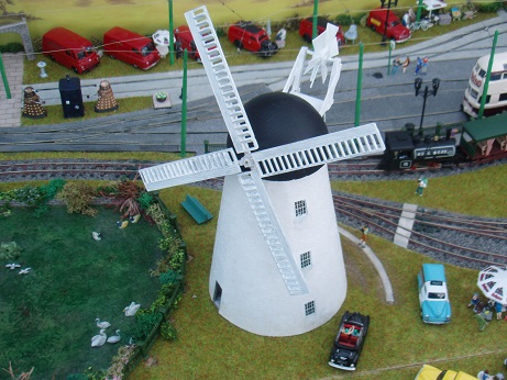
The model is based on nearby Fulwell Mill in Sunderland which was built in 1808 and restored to working order between 1996 and 2001. It has a hemispherical cap with a tail fan which ensures that the sails always face into the wind. As with all our model tramways building the windmill was a joint effort, Gordon built and motorised the mill and Margaret did all the painting and weathering.

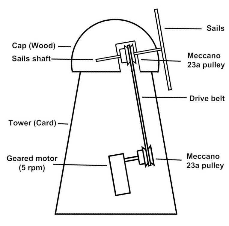
Motorising Diagram

When deciding what to incorporate on to “Foxwood Park”, our model tramway and narrow gauge railway, a windmill was high on the list after the town, tramway and railway buildings.

However when we started to look at ready motorised model windmills we found that that although there were a number available, there did not appear to be a model of a traditional English tower mill.

As we had not built a tapered tower, we looked to the Internet for help where a Japanese website was found which had plans for a Dutch tower mill.

These plans were ideal for building the tower and as downloaded were the correct size for a 00 scale model but after the windmill was built this website disappeared.
 Motor

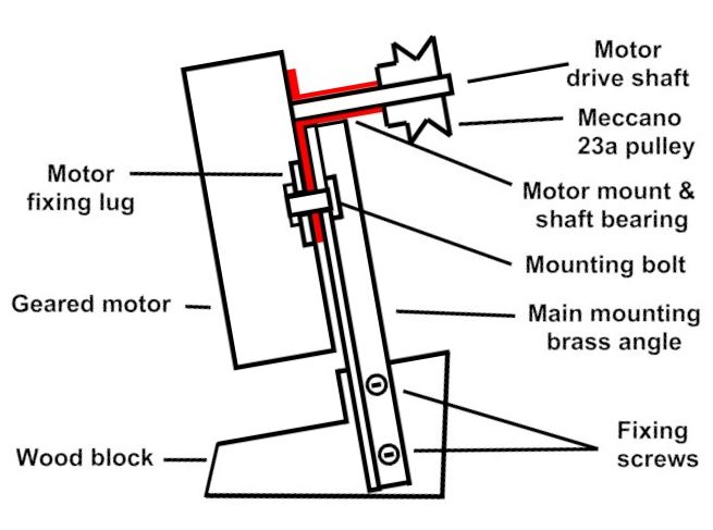
Motor and Mount diagram

The windmill is powered by a geared motor running at 5 r.p.m. recovered from an old fibre-optic Christmas lamp, on a two part mount.

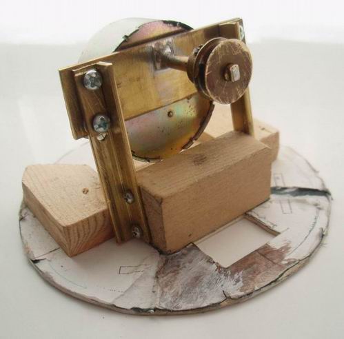
The first part, a combined motor mounting plate and drive shaft bearing, was made from brass strip and tube soldered together.

The second part was made from a piece of wood (easily glued to card) and two pieces of brass angle attached by screws and slotted at the motor end to allow the belt tension to be adjusted.

Motor and Mount

The brass angles are inclined at 10º from vertical so that the drive shaft is parallel to the shaft carrying the sails.

The motor drive shaft (3/16 th inch diameter) was fitted with a Meccano 23a pulley and lubrication inside the mounting tube was by a squirt of WD-40 before assembly.

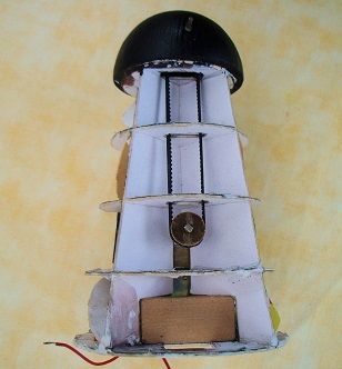
Once the motor and mount were united, using four bolts, with two also mounting the motor, the complete assembly was glued into place on the card base of the tower.

An alternative geared motor which could be used is the Faller No.180629 but it would require a different mount to be constructed.


 Tower

Tower

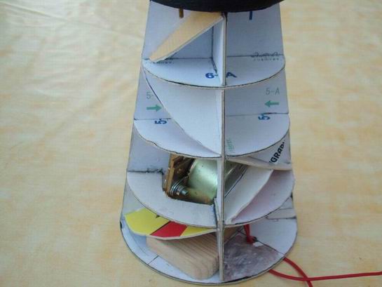
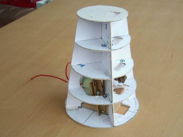
The patterns were printed and glued on to thin card before cutting out and assembling to form the tower. This was then dismantled and the required modifications to clear the angled motor and drive belt were made.

Once the shapes were finalised they were used as patterns for the 1 mm card parts and, after a dry build to check clearances, these parts were assembled and glued around the completed motor and mount.

Braced Tower

The tower was found to be very strong vertically but it could be twisted easily. To stop this, two opposing diagonal braces were added to each level.

The top two levels and the bottom level had the braces in opposite quarters while the third level had both braces in the same quarter.


 Cap

Cap

The hemispherical cap was made from the top of a ball shaped wooden fence post finial. A 1/8 th inch diameter hole was drilled 1/2 inch up from the bottom, angled 10º down towards the centre for the shaft carrying the sails. This made the sails parallel to the mill wall which tapers in at 10º.

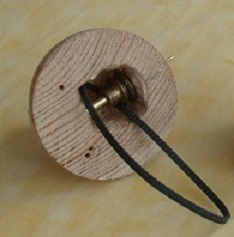
It was then turned over and a 3/4 inch hole drilled so that the first hole went across the centre. This was squared out using a chisel, to make space for the Meccano 23a pulley and drive belt. As the mill is motorised it has been built with the cap fixed and held in place by two brass pins and a screw through the card top of the tower.

This shaft is made from a short piece of 1/16 th square brass tube (to drive the sails) soldered into the end of some round brass tubes to make it up to 1/8 th inch in diameter.

Drive Assembled

The shaft was pushed into the hole drilled into the cap until it appeared in the large hole underneath.

The Meccano 23a pulley, home made brass bush (to fit between the 1/8 th inch shaft and the 3/16 th inch pulley) and drive belt were fitted and the shaft pushed fully home.

The pulley and bush were locked in place against the squared out end of the hole using the grub screw provided.

Lubrication was by a squirt of WD-40 into each part of the cap before assembly.

The base was fitted with two brass locating pins which were connected to the motor feed wires.

The baseboard had matching brass sockets fitted which were connected to the motor feed wires under the board making the mill easier to fit.


 Sails

Sails and Cross

Initially the sails from a Dapol windmill kit were used but It soon became obvious that, as supplied and built, they were too delicate and not suitable for exhibition use.

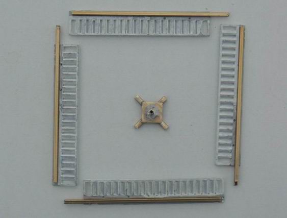
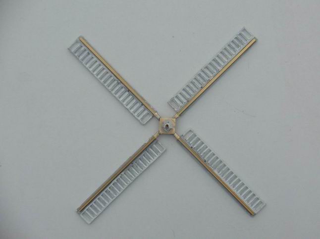
A supporting cross was constructed from brass channel with a square drive tube.


Assembled Sails

This fits over the drive shaft and gives positive drive to the Dapol sails which have each been strengthened by the addition of a 3/32 inch square brass tube glued along the full length.

These tubes were glued into the cross and have made the assembly fit for exhibition use.

Because the mill is so high, the sails need to be removed when Foxwood Park is transported to and from exhibitions when they are stored in their own case.


 Tail Fan

Tail Fan before and after

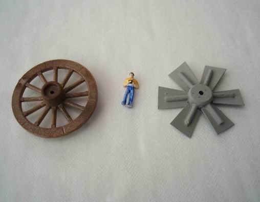
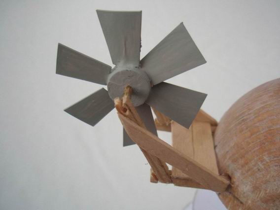
The tail fan was made using a plastic wheel from a Timpo wagon with the hub made narrower and the rim and alternate spokes removed before the Plastikard sails were added.

Tail Fan and Platform

Its supporting platform was made from 1/8th square timber glued into holes drilled in to the rear of the cap and braced with pieces of wooden stirring stick.


 Outer Wall

Outer Wall

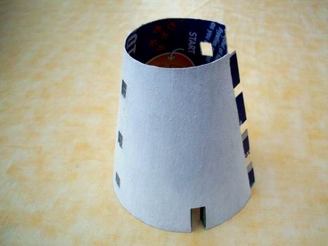
The outer wall was cut from a piece of 0.6 mm card (empty cereal box) using the pattern supplied, and painted with a mixture of white acrylic paint and fine sand.

It was then fitted with windows and doors sourced from stock with the ground floor doors open and the windows in the unseen side of the mill not glazed to allow ventilation for the motor.

When fitted the wall is not attached to the tower, it is just wrapped round and the four tabs on one end are glued to the other end so if it needs to be removed these tabs can be cut by running a sharp knife down the join.


 Completion

Photo of completed windmill with link to video

Before fitting, the cap was painted dark grey with sails, tail fan and supporting platform coloured weathered white.

After assembly the drive to the sails was test run for some time to ensure that it would be reliable. When we were satisfied, that it was not going to cause any problems, the outer wall was fitted around the tower.

The Windmill is fixed in position by two screws, but power for the motor and positive location are provided by two brass pins fitting into brass tube sockets in the baseboard.

To watch a short video of the windmill, click here or click on the photo.


© Gordon Bulmer 2022